Important caveats before you spend time on this:
- This is experimental and there’s a non-zero chance nothing will come out of this.
- One of the components used by this version (btstack) is only free for non-commercial use.
That said I’ve been experimenting with an ESP32-based version of HID Remapper that supports Bluetooth Classic devices (the previously existing nRF52840-based version only supports Bluetooth LE).
If you’re up for some testing, here’s what it currently looks like. It uses an architecture similar to the dual Pico variant with A and B sides, but in this case side A is a Pico (or some other RP2040 board) and side B is an ESP32 board. The ESP32 board receives inputs from Bluetooth devices and sends them to the Pico for processing over serial.
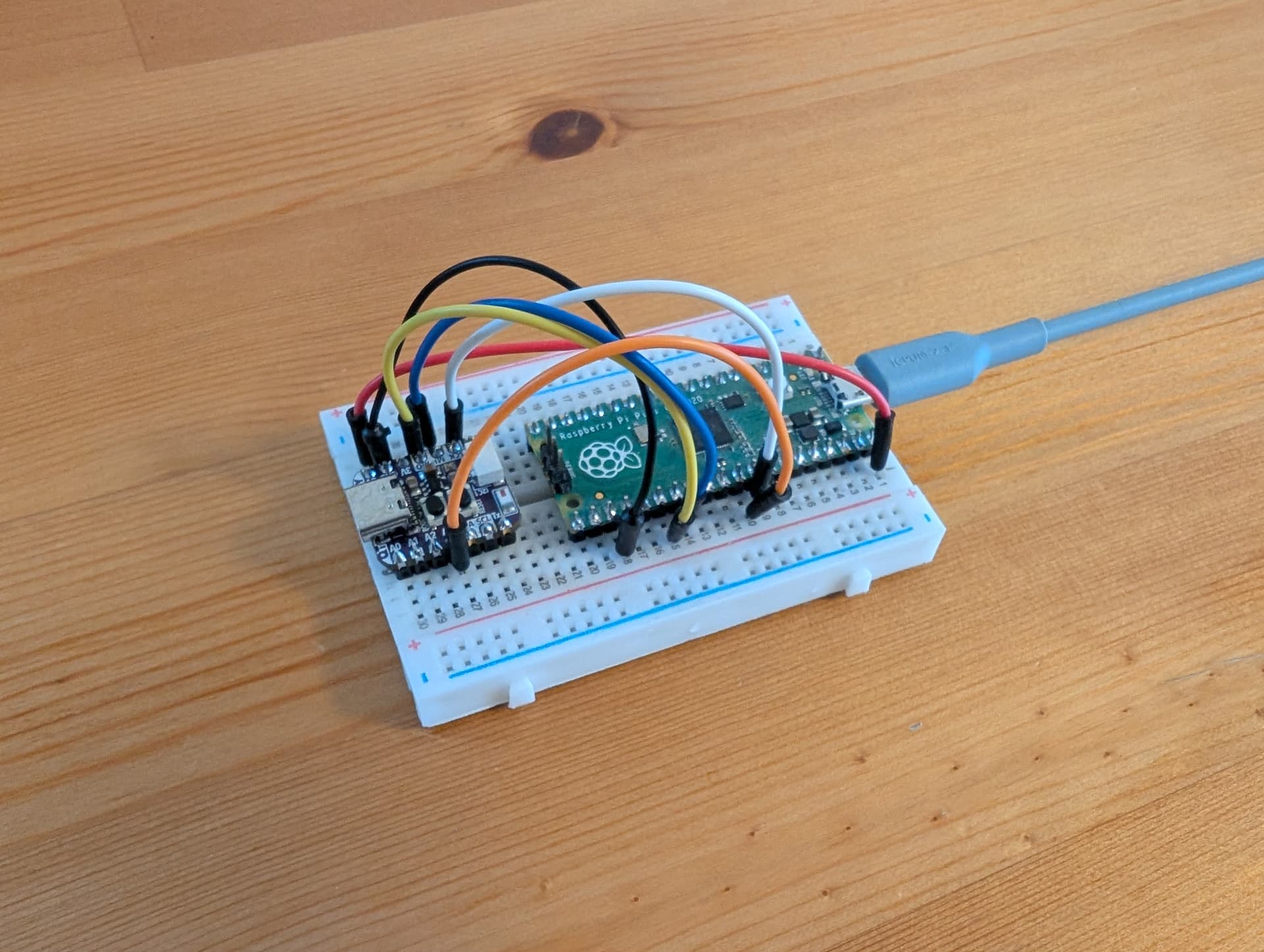
Here’s what you need to build one.
- Raspberry Pi Pico (or another RP2040 board with GPIO 20, 21, 26, 27 pins exposed).
- An ESP32 board with USB and GPIO 12, 13, 14, 15 pins exposed.
Please note the ESP32 board has to be exactly “ESP32”, it can’t be ESP32-C6, ESP32-S3, ESP32-C3 or anything like that. None of the other chips can do Bluetooth Classic. Yes, their naming scheme is confusing.
I tested with the Adafruit QT Py ESP32 Pico board and a LOLIN32 something-or-other. Espressif’s ESP32-DevKit-whatever boards should work fine, just keep in mind they’re too wide to fit on a regular breadboard and still give access to pins on both sides.
It’s good if your board has a 5V input, then you can power it from the Pico.
Make the following connections between the two boards:
| Pico | ESP32 |
|---|---|
| GPIO20 | GPIO13 |
| GPIO21 | GPIO12 |
| GPIO26 | GPIO15 |
| GPIO27 | GPIO14 |
| VBUS | 5V in |
| GND | GND |
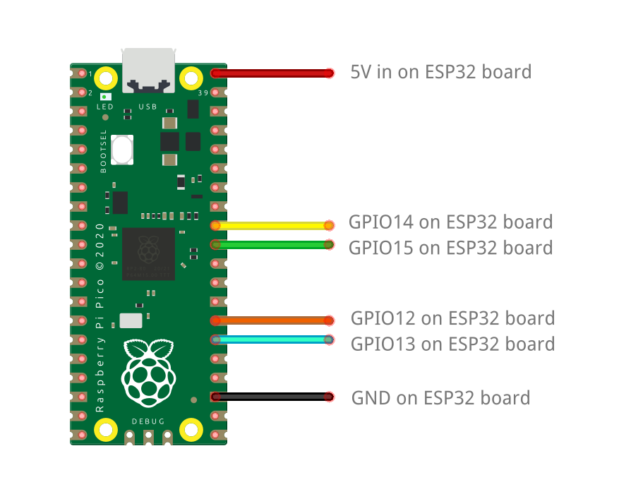
The 5V connection is optional, you can also power the ESP32 board through USB. If you have 5V wired between the boards then only connect the Pico over USB.
This zip contains the experimental firmware for the two boards:
remapper-esp32-test1.zip (490.1 KB)
Connect the boards to your PC one at a time and flash the firmware.
For the Pico the procedure is as usual, hold the BOOTSEL button while connecting the board to the PC, then copy the remapper_bt_a.uf2 file to the “RPI-RP2” drive that should appear.
For the ESP32 board the procedure is a bit more involved.
Open this website in a browser (desktop version of Chrome): https://espressif.github.io/esptool-js/
Where it says “Program”, change the baudrate to 460800 and click “Connect”. Select the serial port for your ESP32 board. If you have more than one port and don’t know which is the correct one, disconnect the board and see which port disappears.
After a few seconds, it should say “Connected to device: …” and additional fields should appear.
Set the “Flash Address” field to “0” (zero). In the “File” field, click “Choose file” and select the remapper_bt_b.bin file.
Click “Program”.
If everything goes well your ESP32 board should now be programmed with the correct firmware.
(I had success with this website on Windows and Mac, if you’re on Linux, you may have to use the command line version of esptool.)
Normal use is the same as the previously existing Bluetooth variant of HID Remapper. There are additional buttons in the “Actions” tab on the configuration website for entering pairing mode and clearing existing pairings. If no device is paired then it enters pairing mode by itself.
The only difference is that there is no LED feedback for when it’s in pairing mode or when a device is connected. If you’re brave you can use the console functionality of the flashing website to look at diagnostic output.
I would be interested in seeing what devices you manage to get this to work with. My expectation is that it should work well with mainstream gamepads, but there might be issues with some mice and keyboards.
Either way let me know.
Please note this doesn’t currently support Bluetooth LE devices. The hardware and library support is there, so it might support it eventually, but it’s currently disabled.