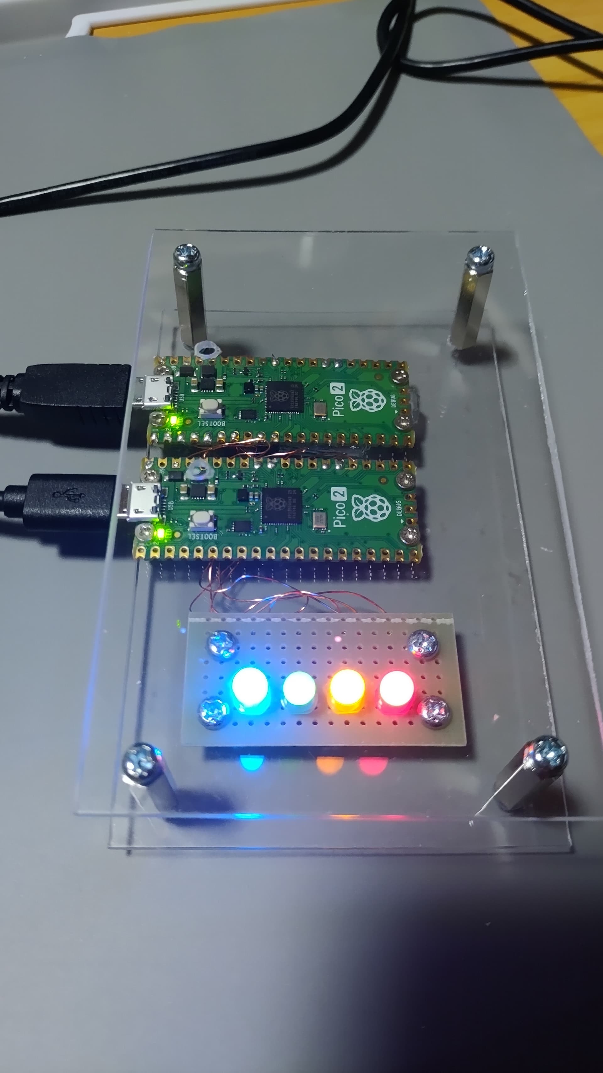
I’ve created a dual version on a Pico2.
I have four LEDs connected to GPIOs 0-3 on side A.
However, the LED on GPIO 0 is always on, even without any input, while the others remain off.
Am I doing something wrong?"
This text is an English translation from Japanese.
Actually I checked again and GPIO 2 and 3 are also reserved on the dual variant (for SWDIO/SWCLK when the A side flashes the B side firmware - typically only used on the custom boards).